
CVT Transmission Housing Forming for Automotive Applications


CVT transmission housing forming commonly combines aluminum high pressure die casting with secondary CNC machining. The housing must support transmission components while providing bearing locations, mounting surfaces, internal cavities, and fluid-related features within a lightweight structure.
For manufacturers, the challenge is not simply producing a large aluminum shell. Complex geometry, changing wall thickness, internal ribs, machining areas, and sealing requirements make transmission housings sensitive to metal flow, porosity, thermal balance, and dimensional variation.
How CVT Transmission Housing Forming Works
Aluminum-silicon die-casting alloys are commonly used for transmission housings. Published gearbox-housing research has used AlSi9Cu3, while industrial transmission-housing applications also commonly reference ADC12-type alloys. The final material should still be selected according to the drawing, mechanical requirements, machining needs, and customer specification.
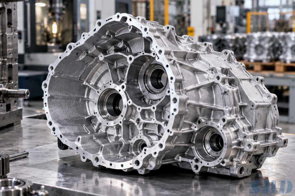
Production usually begins with part and mold analysis. Runners, gates, vents, cooling channels, slides, and cores must allow molten aluminum to fill complex areas while air escapes from the cavity. NADCA notes that metal flow, venting, cooling-line placement, and ejection are fundamental elements of die design, with simulation increasingly used to predict filling behavior.
After casting and trimming, critical areas such as bearing bores, sealing faces, mounting surfaces, and threaded features may require CNC machining.
Why Transmission Housings Are Difficult to Cast
One major challenge is uneven wall thickness. Transmission housings may contain thin walls beside thicker bosses, ribs, or bearing areas. These sections cool at different rates. Local hot spots can produce shrinkage porosity, while difficult flow paths can contribute to incomplete filling or trapped air.
Porosity is particularly important because defects may become exposed during machining or create leakage paths. Industrial research on an automotive transmission case found that melt cleanliness also affected porosity rejection rates, showing that casting quality depends on both mold design and molten-metal control.
Another challenge is dimensional stability. Large housings combine many related bores and mounting surfaces, so casting distortion can create additional difficulty during precision machining.
How Die Casters Solve These Problems
Experienced die-casting engineers generally address transmission-housing problems through several connected measures rather than one adjustment.
Mold-flow simulation can be used to refine runner and gate layouts before tooling is finalized. Venting or vacuum-assisted processes may help reduce trapped gas where internal quality requirements justify them. Shot parameters and die temperature also need stable control.
Cooling deserves special attention. In one published gearbox-housing study, simulation and industrial CT identified a leakage-related defect around a slow-solidifying region. The production team improved the result by introducing localized high-pressure cooling at the affected position.
After casting, CNC machining provides the final accuracy required at critical functional areas. The casting and machining plans should therefore be developed together rather than treated as separate operations.
Where Is the Market for CVT Housings Today?
CVT transmission housings remain relevant for passenger vehicles that continue to use continuously variable transmissions. Current transmission manufacturers still offer CVTs for small, medium, and larger front-wheel-drive vehicles, including hybrid-related transmission products.
At the same time, the automotive powertrain market is changing. Transmission specialists are also expanding into e-axles and integrated electric powertrains.
For die casters, this means experience with lightweight housings, complex cavities, thermal control, machining datums, and sealing surfaces can remain valuable across both conventional and electrified drivetrain programs.
Conclusion
CVT transmission housing forming requires much more than filling a mold with aluminum. Material selection, gating, venting, cooling, porosity control, dimensional stability, and CNC finishing all influence whether the final housing can meet its functional requirements.
The most effective production route starts with the drawing and identifies critical bearing, sealing, mounting, and machining areas before mold development begins.
Transmission Housing Project Support from SHD Precision Die Casting
SHD Precision Die Casting supports custom die-casting project discussions based on customer drawings, 3D models, material requirements, functional surfaces, and downstream machining needs.
For housing-type components, early review of wall thickness, rib structures, machining datums, sealing areas, and potential casting risks can help establish a more practical path from tooling development to finished component production.
Frequently Asked Questions
Q01 | Why are bearing bores usually machined after die casting?
Die casting creates the near-net housing geometry efficiently, while CNC machining can provide tighter control over bearing locations, bore geometry, and relationships between critical mounting features.
Q02 | Does every transmission housing require vacuum die casting?
No. Vacuum assistance depends on the geometry, alloy, internal-quality requirements, sealing requirements, and production process. It should be selected according to the actual defect risk and customer specification rather than applied automatically.
Q03 | What should a buyer provide when requesting a CVT housing quotation?
A useful inquiry should include a 3D model, technical drawing, material specification, critical tolerances, machining areas, expected production quantity, sealing requirements, and any defined inspection criteria.